Phased Arrays
|
If a plane wave is incident upon an antenna array (Figure 1), the phase of the signal at the antennas
will be a function of the angle of arrival of the plane wave. If the signals are then added together,
they may add constructively or destructively, depending on the phases.
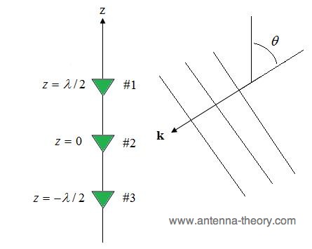 Figure 1. The phase of the signal at each element depends on the angle of arrival of the plane wave.  ) that cancelled out the phase change
due to the propagation of the wave. Then when the signals from each antenna are added together to
form the output of the array, they would combine coherently. This is the fundamental principle used in
phased arrays - also known as beam steering. ) that cancelled out the phase change
due to the propagation of the wave. Then when the signals from each antenna are added together to
form the output of the array, they would combine coherently. This is the fundamental principle used in
phased arrays - also known as beam steering.Lets take an example. Suppose that we had a N=5 element linear array with one-half wavelength spacing between the antennas (assumed to be isotropic for simplicity). The positions are each given by:
 (
 To be absolutely explicit about it, the weight vector can also be written as:
 The resulting Array Factor for this array becomes:
 In the above, k is the wave vector, v(k) is the steering vector, and N=5. The array response is the magnitude of the output, as a function of the incident angle of the plane wave. The array response is identical in form to the radiation pattern of this array (when the same weights are used). This response is shown in Figure 2.
 Figure 2. Response of array versus angle of incidence of a plane wave. Figure 2 captures the fundamental properties of the designed array. First, the array has maximum radiation (or reception) in the direction of (img src="thetad.jpg">), as designed. Second, the array has nulls at roughly 72, 94, 120, and 153 degrees. The null-directions are those in which the array completely blocks signals. This array has an associated HPBW of roughly 30 degrees. Finally, note that the sidelobes are 12 dB below the peak of the main beam. Using a phased-weighting scheme is the simplest of all weighting methods. By employing this method, the array can be steered such that the direction of maximum reception is in a desired direction. The ease of implementation is responsible for its widespread use; however, as we'll see, there are better methods of steering (although the complexity increases). |
 ),
then weights can be applied that are given by:
),
then weights can be applied that are given by: