Loop Antennas
Small Loop AntennasThe small loop antenna is a loop as shown in Figure 1. The antenna feed points would be in series with the loop, such that a small loop looks somewhat like a short circuit across the antenna feed. These antennas have low radiation resistance and high inductive reactance, so that their impedance is difficult to match to a radio impedance (often 50 Ohms). As a result, these antennas are most often used as receive antennas, where impedance mismatch loss can be a bit more easily tolerated in some systems.
The radius is a, and is assumed
to be much smaller than a wavelength (a<<
 Figure 1. Small loop antenna.
Since the loop is electrically small, the current within the loop can be
approximated as being constant along the loop, so that I=
The fields from a small circular loop are given by (note k=2pi/lambda):

The variation of the radiation pattern with direction is given by
The small loop antenna is often referred to as the dual of the dipole antenna, because if a small dipole had magnetic current flowing (as opposed to electric current as in a regular dipole), the fields would resemble that of a small loop. Note that magnetic current is not a real thing, but if you imagine a flow of magnetic charge, the derived fields would be equivalent to a small loop antenna.
While the short dipole has a capacitive impedance (imaginary part of impedance is negative), the impedance of a small loop is inductive (positive imaginary part). The radiation resistance (and ohmic loss resistance) can be increased by adding more turns to the loop. If there are N turns of a small loop antenna, each with a surface area S (we don't require the loop to be circular at this point), the radiation resistance for small loops can be approximated (in Ohms) by:

For a small loop, the reactive component of the impedance can be determined by finding the inductance of the loop, which depends on its shape (then X=2*pi*f*L). For a circular loop with radius a and wire radius p, the reactive component of the impedance is given by:

Examples of practical application of small loop antennas include mobile pagers, NFC antennas, and as field strength probes used in wireless measurements.
The loop antenna feed point does not matter too much - it can be anywhere along the loop perimeter. Note that a balun may be needed, so that the cable that connects the radio (transmitter or receiver) to the loop does not influence the current distribution on the loop antenna.
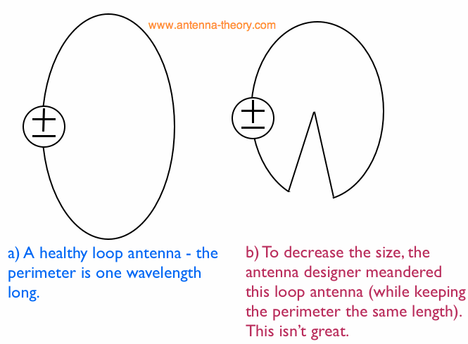
The Loop AntennaAs loop antennas get larger, they become better antennas. A loop antenna will be resonant (with a purely real impedance) as the perimeter of the loop approaches one wavelength in size. Hence, a 300 MHz loop antenna should have a perimeter of 1 meter or larger; a 2.4 GHz loop antenna will only need to be about 12 centimeters in perimeter. The one-wavelength perimeter loop antenna behaves like a folded dipole antenna, with an impedance that is higher than that of a half-wavelength dipole antenna. Robustness of Loop Antennas to the BodyLoop antennas have a very desirable property related to robustness in performance near the human body. To explain this, note that the human body tends to have a large value for permittivity and a bit of conductivity. The permittivity acts on the Electric Field and tends to tune the response of the antenna down in frequency. The conductivity of the body acts as a lossy material and absorbs energy from the antenna; this can severly degrade the antenna efficiency. The human body affects dipole antennas particularly strongly. This is because in the near field (very close to the antenna), the Electric Fields are particularly strong. Interestingly, the body isn't really magnetic (i.e. does not have a large permeability). Hence, the magnetic fields are not significantly perturbed by the human body, and hence aren't affected like the electric fields are. And because the loop antenna is somewhat the "dual" of the dipole as discussed earlier, the magnetic fields are strong in the near field of the loop antenna. These magnetic fields ultimately give rise to the antenna radiation, and since they are somewhat immune to the human body, loop antennas tend to be much more robust in terms of performance when they are placed near a human. As a result, antennas in hearing aids and other "wearable antennas" are often loop antennas. This property makes loop antennas extremely useful. Loop Antenna ShapesIt turns out the loop antenna does not need to be a perfect circle (as in Figure 1), or a tight rectangle as in the folded dipole case. The main parameter of interest is the perimeter length, which should be about a wavelength. Therefore, the enclosed loop area is not as important a parameter as the perimeter length. One note: it is not a great idea to meander the loop to increase the length. This causes the current to somewhat cancel and introduces capacitance to the loop, which degrades the efficiency and bandwidth of the antenna. A loop antenna designer may try to shrink the size of the loop antenna by meandering. This is illustrated in Figure 2:
 Figure 2. Loop Antenna Shapes - Meandering is Bad.
Antennas Tutorial (Home)
This page on loop antennas and small loops is copyrighted, but can be reproduced with citation. No permission needed. Copyright antenna-theory.com, 2009-2020.
|
 ).
The loop lies in
the x-y plane.
  .
. , so that the radiation pattern of a small loop antenna
has the same power pattern as that of a