Fractal Antenna
|
Antenna designers are always looking to come up with new ideas to push the envelope for antennas, using a smaller volume while striving for every higher bandwidth and antenna gain. One proposed method of increasing bandwidth (or shrinking antenna size) is via the use of fractal geometry, which gives rise to fractal antennas. FractalsFractals are those fun shapes that if you zoom in or zoom out, the structure is always the same. They have wild properties, like having a finite area but infinite perimeter. They are often constructed via some sort of iterative mathematical rule, that generates a fractal from a simple object step by step. In the last section of this page, we will do that in designing a fractal antenna. Examples of fractal geometry are shown in Figures 1 and 2: 
Figure 1. A snail like fractal geometry.
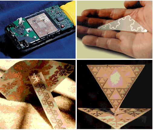
Figure 2. Triangle Fractal Geometry. Fractal AntennasSince fractals show up in the real world of nature (snail shells, leaves on a tree, pine cones), why not see if they perform well as antennas? It turns out that if you make antennas with fractal shapes, they will radiate, and often have multiband properties. Exmaples of these antennas are below:
 Figure 3. Triangle Fractal Geometry. Upper Left: Patch Antenna Fractal. Lower Left: Monopole Fractal. Lower Right: Bowtie Monopole Fractal Antenna .
Analysis of Fractal AntennasThe argument on why you might want to use a fractal geometry essentially is "if you have a very complex shape, you will allow for many electric current modes (i.e. distinct current distributions) to exist, all of which can give rise to radiation. As a result, a complex fractal antenna should have very wide bandwidth, and because the lengths of the traces are very long the antenna will be smaller than otherwise need to be". This is a valid argument, and some people love fractal antennas. It certainly sounds intelligent. Having never encountered a situation where a fractal antenna has been used, I decided to build up a triangle fractal antenna and test it, as I evolve it from a simple bowtie antenna through iterations to become a fractal. Let's see what happens. The length is approximately 7 inches (18cm) and the width is about 3.5 inches (9cm). I start with a simple bow-tie antenna as shown in Figure 4:
 Figure 4. A bowtie antenna - this is our baseline antenna for comparison. I will then use an iteration approach, each time making the triangle antenna approach the geometry of the fractal in Figure 2. The first step is to remove a couple triangles, such that we have 3 idential triangles on each side of the antenna:
 Figure 5. Iteration 1 of the evolution from bowtie to fractal antenna. We then repeat that same process on each triangle - this is the iteration method that will give rise to the fractal. Iteration 2 makes for 18 total triangles that make up the antenna:
 Figure 6. Iteration 2 of the evolution from bowtie to fractal antenna. Finally, for fun we'll add antoher iteration, ending up with 54 total triangles, and an ever more complicated structure approaching a fractal:
 Figure 7. Iteration 3 of the evolution from bowtie to fractal antenna. Now, to test these antennas, we will measure the VSWR and the antenna efficiency at each stage and compare the results. The VSWR results are shown in Figure 8:
 Figure 8. VSWR for the Bowtie and Iterations 1-3 of the fractal Antenna. Figure 8 shows that the baseline case and the antennas of Figures 5-7 (iterations 1,2,3) are not significantly different. There are some frequency regions where the fractals are better (such as around 4 GHz), and some places where the baseline case is better (about 5 GHz). From Figure 8, the conclusion is that there is no fundamental benefit to performing the fractal iteration over a bowtie antenna from a VSWR (mismatch loss) perspective. Next, we look at the antenna efficiency. This is shown in Figure 9:
 Figure 9. Antenna Efficiency for the Bowtie and Iterations 1-3 of the fractal Antenna. Figure 9 is very interesting. At the low frequencies (700MHz-1.5 GHz), the baseline case performs better than the fractals. In fact - as each iteration occurs on the bowtie geometry, the low frequency antenna efficiency gets worse. This is very interesting. One of the reasons fractal antennas are touted as valuable is that they are able to shrink the size of the antenna - if this were the case, the lowband efficiencies should get better with each iteration. There are some regions where fractals appear to have better performance - 2 GHz and 3.5 GHz (for instance) - but it is not significantly better. In fact, there are wide bandwidths where performing the iteration to make the fractal actually degrades the antenna efficiency. Hence, this data shows that implementing a triangle fractal (of Figure 2) as an antenna adds little to no value, and can often degrade performance. This is very interesting. It implies that a lot of the talk around fractal antennas is in fact hype. If you have a volume available to you for antenna design, it is best to use a large conducting area (as in Figure 5 - no cut outs or meandering). It is not advantageous to increase manufacturing and design complexity by creating fractals. This may explain why fractals are not widely used. There is some talk of fractals used in defense applications. I honestly am not sure if this is because the defense industry is significantly less (or more) intelligent than other industries (due to government ownership), or if there exists some advantages to some types of fractal antennas. But it just goes to show - test things out and see for yourself! I hope you've enjoyed this article and learned a thing or two about fractal antennas. Tell your friends!
Antennas (Home)
|
