Transmission Lines: Input Impedance
|
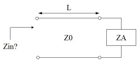
We are now ready to determine the input impedance of a transmission line of length L
attached to a load (antenna) with impedance ZA. Consider the following circuit:
 In low frequency circuit theory, the input impedance would simply be ZA. However, for high-frequency (or long) transmission lines, we know that the voltage and the current are given by:
 For simplicity, assume the transmission line is lossless, so that the propagation constant is purely imaginary. If we define z=0 to be at the terminals of the load or antenna, then we are interested in the ratio of the voltage to the current at location z=-L:
 Using the definition for gamma (the voltage reflection coefficient), the above equation can be manipulated algebraically, and when evaluated at z=-L, we obtain:
 This last equation is fundamnetal to understanding transmission lines. The input impedance of a load ZA is transformed by a transmission line as in the above equation. This equation can cause ZA to be transformed radically. An example will now be presented.
ExampleConsider a voltage source, with generator impedance Zg, hooked to an antenna with impedance ZA via a transmission line. Suppose that Zg=50 Ohms, ZA=50 Ohms, Z0=200 Ohm, and that the line is a quarterwavelength long. How much power does the generator deliver? Answer: The diagram for this problem is given in the following diagram:
 The above diagram also shows the "equivalent circuit". The input impedance becomes:
 Hence, the current that flows is given by:
 Note that if high frequency circuit theory was not taken into account, the current flow would have been V/100 Amps. This illustrates how transmission lines can upset the expected operation of high frequency circuits. In the next section, we'll look at ways we can exploit the transmission line characteristics for our benefit. This is very useful for impedance matching, which enables maximum power transfer from a load to (or from) a receiver (a generator).
|
Previous: Reflection Coefficient and VSWR