Yagi-Uda Antenna
|
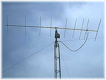
The Yagi-Uda antenna or Yagi Antenna is one of the most brilliant antenna designs. It is simple to construct and has a high gain, typically greater than 10 dB. The Yagi-Uda antennas typically operate in the HF to UHF bands (about 3 MHz to 3 GHz), although their bandwidth is typically small, on the order of a few percent of the center frequency. You are probably familiar with this antenna, as they sit on top of roofs everywhere. An example of a Yagi-Uda antenna is shown below.
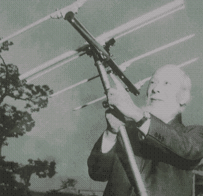
 The Yagi antenna was invented in Japan, with results first published in 1926. The work was originally done by Shintaro Uda, but published in Japanese. The work was presented for the first time in English by Yagi (who was either Uda's professor or colleague, my sources are conflicting), who went to America and gave the first English talks on the antenna, which led to its widespread use. Hence, even though the antenna is often called a Yagi antenna, Uda probably invented it. A picture of Professor Yagi with a Yagi-Uda antenna is shown below.

In the next section, we'll explain the principles of the Yagi-Uda antenna.
Yagi Antenna Design Parameters
Geometry of Yagi Antennas
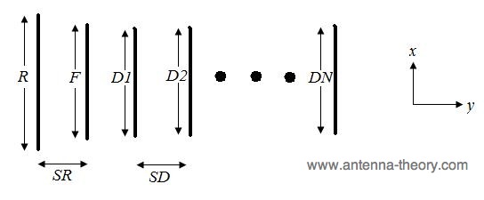
The basic geometry of a Yagi-Uda antenna is shown below in Figure 1.
 Figure 1. Geometry of Yagi-Uda antenna.
The Yagi antenna consists of a single 'feed' or 'driven' element, typically a dipole or a folded dipole antenna. This is the only member of the above structure that is actually excited (a source voltage or current applied). The rest of the elements are parasitic - they reflect or help to transmit the energy in a particular direction. The length of the feed element is given in Figure 1 as F. The feed antenna is almost always the second from the end, as shown in Figure 1. This feed antenna is often altered in size to make it resonant in the presence of the parasitic elements (typically, 0.45-0.48 wavelengths long for a dipole antenna).
The element to the left of the feed element in Figure 1 is the reflector. The length of this element is given as R and the distance between the feed and the reflector is SR. The reflector element is typically slightly longer than the feed element. There is typically only one reflector; adding more reflectors improves performance very slightly. This element is important in determining the front-to-back ratio of the antenna. Having the reflector slightly longer than resonant serves two purposes. The first is that the larger the element is, the better of a physical reflector it becomes.
Secondly, if the reflector is longer than its resonant length, the impedance of the reflector will be inductive. Hence, the current on the reflector lags the voltage induced on the reflector. The director elements (those to the right of the feed in Figure 1) will be shorter than resonant, making them capacitive, so that the current leads the voltage. This will cause a phase distribution to occur across the elements, simulating the phase progression of a plane wave across the array of elements. This leads to the array being designated as a travelling wave antenna. By choosing the lengths in this manner, the Yagi-Uda antenna becomes an end-fire array - the radiation is along the +y-axis as shown in Figure 1.
The rest of the elements (those to the right of the feed antenna as shown in Figure 1) are known as director elements. There can be any number of directors N, which is typically anywhere from N=1 to N=20 directors. Each element is of length Di, and separated from the adjacent director by a length SDi. As alluded to in the previous paragraph, the lengths of the directors are typically less than the resonant length, which encourages wave propagation in the direction of the directors.
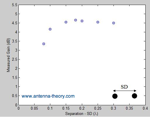
The above description is the basic idea of what is going on with the Yagi-Uda antenna. Yagi antenna design is done most often via measurements, and sometimes computer simulations. For instance, let's look at a two-element Yagi antenna (1 reflector, 1 feed element, 0 directors). The feed element is a half-wavelength dipole, shortened to be resonant (gain = 2.15 dB). The gain as a function of the separation is shown in Figure 2.
 Figure 2. Gain versus separation for 2-element Yagi antenna.
The above graph shows that the gain is increased by about 2.5 dB if the separation SD is between 0.15 and 0.3 wavelengths. Similarly, the gain for this Yagi antenna can be plotted as a function of director spacings, or as a function of the number of directors used. Typically, the first director will add approximately 3 dB of overall gain (if designed well), the second will add about 2 dB, the third about 1.5 dB. Adding an additional director always increases the gain; however, the gain in directivity decreases as the number of elements gets larger. For instance, if there are 8 directors, and another director is added, the increases in gain will be less than 0.5 dB. In the next section on Yagis, I'll go further into the design of Yagi-Uda antennas.
Top: Introduction to Yagi Antennas Antenna Theory (Home)
|