Spiral Antennas
|
Spiral antennas belong to the class of "frequency independent" antennas; these antennas are characterized as having a very large bandwidth. The fractional Bandwidth can be as high as 30:1. This means that if the lower frequency is 1 GHz, the antenna would still be efficient at 30 GHz, and every frequency in between. Spiral antennas are usually circularly polarized. The spiral antenna's radiation pattern typically has a peak radiation direction perpendicular to the plane of the spiral (broadside radiation). The Half-Power Beamwidth (HPBW) is approximately 70-90 degrees. Spiral antennas are widely used in the defense industry for sensing applications, where very wideband antennas that do not take up much space are needed. Spiral antenna arrays are used in military aircraft in the 1-18 GHz range. Other applications of spiral antennas include GPS, where it is advantageous to have RHCP (right hand circularly polarized) antennas.
The Log-Periodic Spiral AntennaIn 1954, Edwin Turnur started messing with a dipole antenna. Instead of leaving the arms straight, he wrapped them around each other, forming a spiral. This was the beginning of the spiral antenna. We can define the arms of a spiral antenna using simple polar coordinates and polar functions. The log-periodic spiral antenna, also known as the equiangular spiral antenna, has each arm defined by the polar function:
In Equation [1],
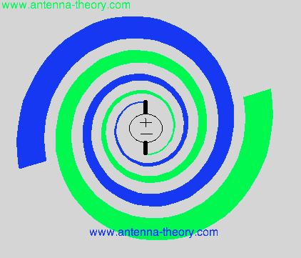 Figure 1. Log-Periodic Spiral Antenna with C = 1 and a = 0.1. The planar spiral antenna of Figure 1 will have peak radiation directions into and out of the screen (broadside to the plane of the spiral, in both the front and the back). The spiral antenna of Figure 1 will radiate Right Hand Circularly Polarized (RHCP) fields out of the screen, and Left Hand Circularly Polarized (LHCP) fields into the screen. The sense of the circularly polarized fields can be determined by placing your thumb in the direction of the fields, and curling your fingers in the direction of the spiral antenna (If your fingers curl the right way using your right hand, then it is RHCP. Otherwise, it is LHCP). The parameters that effect the radiation of the spiral antenna include:
1. Total Length of the Spiral, or the outer radius
(
2. The Flare Rate (a) - The rate at which the spiral grows with angle is the flare rate. If a is too small, the spiral is tightly wrapped around itself. In this case, it will behave more like a capacitor, with closely coupled conductors, giving poor radiation. If the flare rate is too large, the spiral acts more like a dipole as it doesn't wrap around itself. A commonly used value is a = 0.22.
3. Feed Structure -
The feed must
be controlled with a balun
so that the spiral has balanced currents on either arm. A commonly used balun for spiral antennas
is the infinite balun.
More importantly, the feed structure determines the high end of the operating band. How tightly you can wrap the spiral in on itself
determines how small the wavelength can be that will fit on your spiral and still maintain spiral antenna operation. The highest frequency in the spiral antenna's
operating band occurs when
the innermost radius of the spiral (i.e. where the spiral starts after the feed structure) is equal to lambda/4 (one quarter wavelength). That is,
the highest frequency can be determined from the inner radius
(
4. Number of Turns (N) - The number of turns of the spiral is also a design parameter. Experimentally, it is found that spirals should have at least one-half turn. Spiral with up to 3 turns work well, with N=1.5 turns being a common number. Radiation occurs from the spiral antenna when the currents on the spiral's arms are in phase. As the spiral winds outward from the center, there will exist some region for each frequency (wavelength) where the currents add constructively and produce radiation. This radiation removes energy from the electric current on the spiral antenna; as a result, the magnitude of the current dies off with distance from the spiral antenna. Hence, there is little reflection of current from the end of the spiral antenna. How quickly the current decreases in magnitude away from the center of the spiral is a function of the geometry of the spiral antenna. To furthur reduce reflection from the end of the spiral, sometimes resistive loads are applied to the end of spirals to keep current from reflecting at the end of the spiral arms. This will decrease overall antenna efficiency.
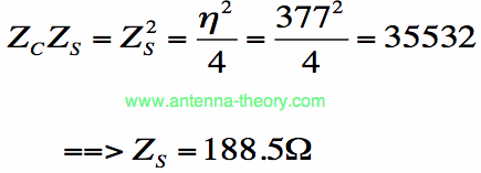
Impedance of Slot Antenna - Babinet's PrincipleTo estimate the impedance of the spiral antenna, we can recall Babinet's Principle, which was discussed with respect to slot antennas. Note that the Log-Periodic Spiral Antenna and it's dual surface are identical. That is, if we rotate the Log-Periodic Spiral by 90 degrees, we get the exact same shape, which is the dual of the spiral antenna. This unique property means has a nice consequence. Since the impedance of two antennas that are identically shaped must also be identical, we can obtain the impedance from Babinet's principle:
That is, the Log-Periodic Spiral Antenna has a theoretical impedance of about 188 Ohms. In actual realizations of Spiral antennas the impedance tends to be less than this, in the 100-150 Ohm range.
Radiation PatternsThe radiation pattern of the Log-Periodic Spiral Antenna is approximately given by:
This pattern has two equal radiation peaks, both broadside to the plane of the spiral antenna (which lies in the z=0 plane, or x-y plane). One peak is above
the planar spiral antenna and the other is below. The Spiral Antenna has circular polarization over a wide beamwdith, often for angular regions as wide as
The Archimedean Spiral AntennaAnother common planar spiral antenna type is known as the Archimedean Spiral antenna. Each arm of the Archimedean spiral is defined by the equation:
Equation [6] states that the radius r of the antenna increases linearly with the angle
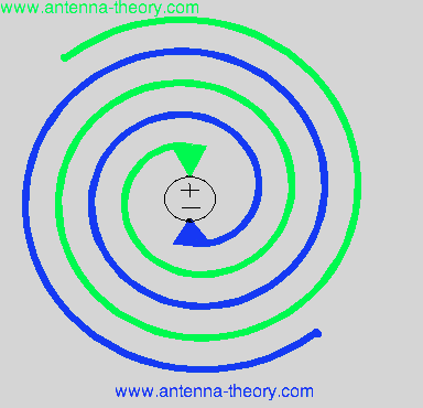 Figure 2. Archimedean Spiral Antenna, with a = 0.1. In Figure 2, we have two arms of the Archimedean spiral antenna flaring away from the center, as defined by Equation [6]. The feed of the antenna (the voltage source), is placed directly across between the two arms of the spiral - the positive end to one arm and the negative end of the feed to the second spiral arm.
Cavity-Backed Slot AntennasThe slot antennas described previously have been planar slot antennas. As discussed, they are commonly used on aircraft or other metal-backed objects. As such, it is desirable to design the slot antenna to be cavity-backed by some metal. This isolates the spiral antenna from what is behind it, so that it can be mounted on objects without worrying about retuning the antenna. Cavity-backed slots come in two types. The first is a simple metallic backing separated from the spiral by some distance or depth, d. This metallic backing will causes reflections of the radiated fields that enter the cavity. As such, they can often cancel the fields travelling broadside to the plane of the spiral antenna. If the depth d is small relative to a wavelength, or an integer multiple of a half-wavelength, the reflected field will tend to cancel the forward travelling field of the spiral antenna, thus leading to poor radiation. Hence, doing a metallic cavity-backed spiral will work, but will decrease the wideband characteristics of the spiral antenna. An alternative method is to use an absorbing material to cavity back the spiral antenna. In this scenario, the reflected fields from the cavity will be attenuated, so that there is no destructive interference; hence, the spiral antenna will maintain its wideband characteristics. This tends to decrease the antenna efficiency of the spiral antenna, since roughly half the radiated power should be absorbed (the fields travelling into the cavity). However, this loss of efficiency is approximately 3 dB, which is often tolerable.
Simple Construction of an Archimedean Spiral Antenna
In this section, I'll discuss the simple construction of a planar Spiral Antenna. First, here are some Spiral Antenna Patterns you can print out if you want to create your own spiral antennas: Archimedean Spiral, a = 0.22, Approximately 3.2 Turns Log-Periodic Spiral Antenna, a = 0.2, Approximately 2.5 Turns I start with the printout of the Archimedean Spiral Antenna. I then use two coaxial cables of about 15 inches long:
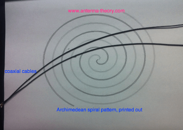 I begin with the feed coaxial cable, and wrap it towards the center of the spiral (this will be spiral arm 1). It is important to have the spiral arms be made of identical materials and shapes, to keep the current balanced. As such, I feed the center conductor of the feed cable (spiral arm 1) to the outer shielf of the second coaxial cable (spiral arm 2). I then wrap Spiral Arm 2 out along the second path of the spiral antenna (green line) in the above Archimedean image. I then simply use tape to secure the antenna in place. That's it! We have our spiral antenna, shown with the feeding coaxial cable connected:
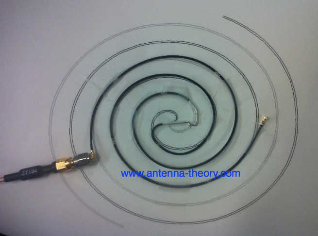 Note that we used the feed cable itself as one arm of the Spiral Antenna, making an infinite balun. The VSWR measured with a network analyzer (VNA) is shown in Figure 3:
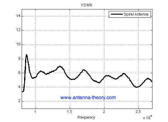 Figure 3. VSWR for the Spiral Antenna Shown Above. The VSWR in Figure 3 isn't particularly well matched (a little less than 50% mismatch loss across the band). However, the VSWR is farely constant, which is a desirable property of broadband antennas. The VSWR for this antenna could be improved via optimization of the feed structure, increasing the number of turns and optimizing the shape (how quickly the spiral winds, or using the Log-Periodic Spiral Shape). However, this is pretty good for a 5-minute antenna. The antenna efficiency is shown in Figure 4:
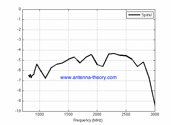 Figure 4. Efficiency of Constructed Spiral Antenna. The efficiency remains fairly constant, at about -5 dB (31.6%) across the band. With the mismatch loss being about 3 dB, there appears to be about 2 dB of loss associated with the antenna structure itself (such as conductor losses). Hence, there is a good amount of optimization that can occur to improve the performance of the spiral antenna. However, Figure 4 shows that this antenna is a decent wideband radiator.
Antenna Tutorial (Home)
|

 is a constant that controls the initial radius of the spiral antenna. The parameter a controls the rate at which the spiral
antenna flares or grows as it turns. Equation [1], in English, states that the spiral antenna radius grows exponentially as it turns. In Figure 1, a plot
of a planar Log-Periodic Spiral Antenna is shown.
 )
- This determines the lowest frequency of operation for the spiral antenna. The lowest operating
frequency of the spiral antenna
is commonly approximated to occur when the wavelength is equal to the circumference of the spiral:


 .
This is a very broad beamwidth for circular polarization; this is one
of the features that makes spiral antennas very useful.
 . The parameter a is simply
a constant that controls the rate at which the spiral flares out. The second arm of the Archimedean spiral the same as the first, but rotated 180 degrees.
A plot of the Archimedean spiral given in Equation [6] is shown in Figure 2: