The Parabolic Reflector Antenna (Satellite Dish)
|
The most well-known reflector antenna is the parabolic reflector antenna, commonly known as a
satellite dish antenna. Examples of this dish antenna are shown in the following Figures.

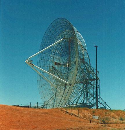
Figure 1. The "big dish" antenna of Stanford University.
Figure 2. A random direcTV dish antenna on a roof. Parabolic reflectors typically have a very high gain (30-40 dB is common) and low cross polarization. They also have a reasonable bandwidth, with the fractional bandwidth being at least 5% on commercially available models, and can be very wideband in the case of huge dishes (like the Stanford "big dish" above, which can operate from 150 MHz to 1.5 GHz). The smaller dish antennas typically operate somewhere between 2 and 28 GHz. The large dishes can operate in the VHF region (30-300 MHz), but typically need to be extremely large at this operating band. The basic structure of a parabolic dish antenna is shown in Figure 3. It consists of a feed antenna pointed towards a parabolic reflector. The feed antenna is often a horn antenna with a circular aperture.
 Figure 3. Components of a dish antenna. Unlike resonant antennas like the dipole antenna which are typically approximately a half-wavelength long at the frequency of operation, the reflecting dish must be much larger than a wavelength in size. The dish is at least several wavelengths in diameter, but the diameter can be on the order of 100 wavelengths for very high gain dishes (>50 dB gain). The distance between the feed antenna and the reflector is typically several wavelenghts as well. This is in contrast to the corner reflector, where the antenna is roughly a half-wavelength from the reflector. In the next section, we'll look at the parabolic dish geometry in detail and why a parabola is a desired shape.
Geometry of Parabolic Dish AntennaNow we'll try to explain why a paraboloid makes a great reflector. To start, let the equation of a parabola with focal length F can be written in the (x,z) plane as:
 This is plotted in Figure 4.  Figure 4. Illustration of parabola with defining parameters.
The parabola is completely described by two parameters, the diameter D and the focal length F.
We also define two auxilliary parameters, the vertical height of the reflector (H) and the max
angle between the focal point and the edge of the dish (
 Figure 5. Two rays leaving the focal point and reflected from the parabolic reflector. There are two observations that can be made from Figure 5. The first is that both rays end up travelling in the downward direction (which can be determined because the incident and reflected angles relative to the normal of the surface must be equal). The rays are said to be collimated. The second important observation is that the path lengths ADE and ABC are equal. This can be proved with a little bit of geometry, which I won't reproduce here. These facts can be proved for any set of angles chosen. Hence, it follows that:
As a result of these observations, it follows the distribution of the field on the focal plane will be in phase and travelling in the same direction. This gives rise to the parabolic dish antennas highly directional radiation pattern. This is why the shape of the dish is parabolic. Finally, by revolving the parabola about the z-axis, a paraboloid is obtained, as shown below.
 In the next section, we'll look at gain calculations for a parabolic reflector antenna.
Antennas (Home)
|

 ). These parameters are related
to each other by the following equations: